SWAMP CREEK & WESTERN
RAILROAD ASSOCIATION
211 Railroad Ave. Edmonds, WA 98020
LAYOUT ELECTRICAL MANUAL
Established December 5, 2000
Revised by page
I. GENERAL WIRING PRACTICES
|
Layout Electrcial Manual Index |
I. GENERAL WIRING PRACTICES:
The guidelines set forth in this manual are done both to establish standard wiring practices for installation as well as aid SC&W members in maintenance, fault finding and repair.
All electrical projects for the layout shall be fully described in writing and approved by the Electrical Department Head and the Second Vice President before any such installation is performed.
DRAWINGSThe electrical drawings here in shall be in the care of the Electrical Department Head and the Second Vice President.
The draftsman will hold onto the originals and distribute field copies as necessary.
At such times as deemed necessary updated copies will be distributed. At that time all outdated copies should be discarded or marked "OBSOLETE" with the date.
In certain cases it might be necessary for a member or another department to inform the Electrical Department of a change or error on the drawings. The procedure for this will be to make a copy of the particular drawing and mark it with the corrections and/or changes. Use a yellow pencil to mark the things to be removed. Use a red pencil to mark the things to be added. Write a brief description and the reason for the change and submit it to the Electrical Department Head or the Second Vice President for action.
TEXTThe official Electrical Manual master copy shall be in the care of the Electrical Department Head and the Second Vice President.
In certain cases it might be necessary for a member or another department to inform the Electrical Department of a change or error on the text. The procedure for this will be the same as explained for drawings. Or the correction may be submitted in electronic form, in WORD for Windows. Strike through the existing text for deletions and use italics for additions. Write a brief description and the reason for the change and submit it to the Electrical Department Head or the Second Vice President for action.
- All wiring projects shall adhere to the color codes that have been set forth in this manual.
- All wiring projects will used the appropriate gauge and type of wire specified.
- All wiring will follow the wiring trunk line or the layout bench work, along the top side and shall be properly secured. In all cases the wires should not be allowed to dangle below the bench work.
- One should always use skill and care in installation and maintenance. If you are not qualified to do the job please ask for help.
Refer to SC&W Standards and Procedures: 6.H Layout, Electrical:
- All electrical construction and maintenance shall be done under the guidance of the Second Vice President (2nd VP) and Electrical Department. The Electrical Department shall be lead by the Wire Chief, a standing position held by the most knowledgeable member of such as deemed by the Executive Committee. Other members may be added to the Electrical Department with the approval of the Executive Committee.
- All electrical work shall be done with due care, skill and knowledge. If a procedure is not fully understood it shall not be attempted.
- The Electrical Department and the 2nd VP shall create and maintain documentation on all aspects of the association's electrical work including standard procedures, layout wiring schematics, manufacturer's documentation and schematics.
- Standard electrical procedures shall:
- Carefully consider the manufacturer's recommendations on installation and use.
- Establish and follow the correct SC&W RR wiring diagrams and color codes.
- Use the proper size and type of wire.
- Use the proper components, connections, termination and voltages.
- Be done neat and orderly, properly dressed and secured.
- Be properly tested before being put into general service.
- Leave no hazardous voltages exposed.
- Adhere to lawful codes.
- Component installations shall be carefully controlled. All such work must be explicitly pre-approved by both the 2nd VP and Wire Chief.
- All electrical faults shall be reported immediately to the Electrical Department by filling out a trouble ticket and posting it in the usual manner.
- Maintaining mainline operations shall always have the highest priority. Projects that might interrupt a regularly scheduled operating session must have pre-approval by membership vote.
C. WIRES AND WIRING COLOR CODES:
1. TRACK POLARITY
Conventional 18 volt direct current (DC) throttles power our trains through the rails.
The plus side of the power to the track is set up with the old West Coast practices (1945-1960) of Engineer's right, (right side) heading **west** from Orchard's mainline at the passenger station. Negative will be the rail closest to you at this point, but follow it around the layout noting that as the track turns back around on itself along the back wall. The negative rail will be away from you at all other locations on the layout.
The rule is: positive (+) on right, westbound.
The throttles are wired so the direction switch on the controllers is in the "up" position when westbound. You can remember this by thinking of your train sitting in Orchard and you go "up" the hill, westbound, towards Rimrock and on to Port Columbia.
The positive (+) power rail is typically connected with YELLOW wires and the negative (-) common rail with BLUE on the mainline. See the next chart for branch and yard wire color codes.
The tail sections of the hidden return loops are wired with bridge rectifiers which only allow outbound train movements through these track sections. The direction of travel in the loops shall therefore be restricted to a counter-clockwise direction.
The hidden return loop tracks are also independently isolated for staging purposes. They are wired through color coded feeder wires as explained in Section IX of this manual.
And note that track polarity of the loops is opposite in respect to one another.
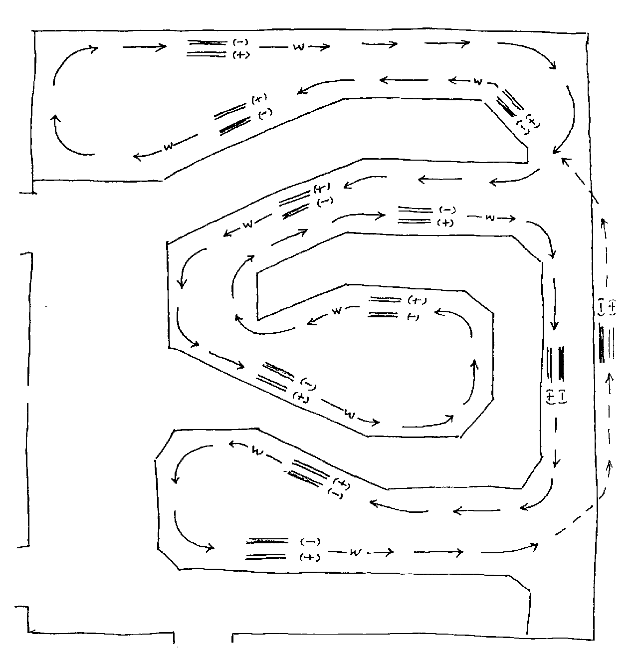
TRACK POLARITY ( - ) BLUE ( + ) YELLOW
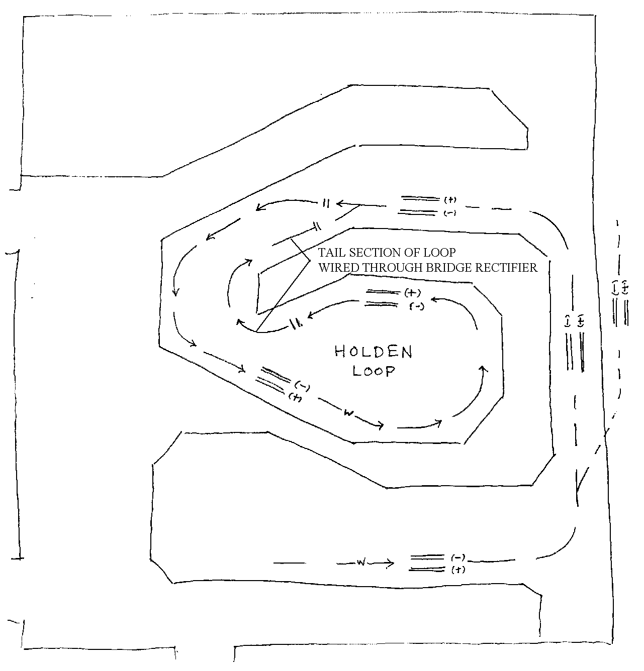
TRACK POLARITY HOLDEN RETURN LOOP
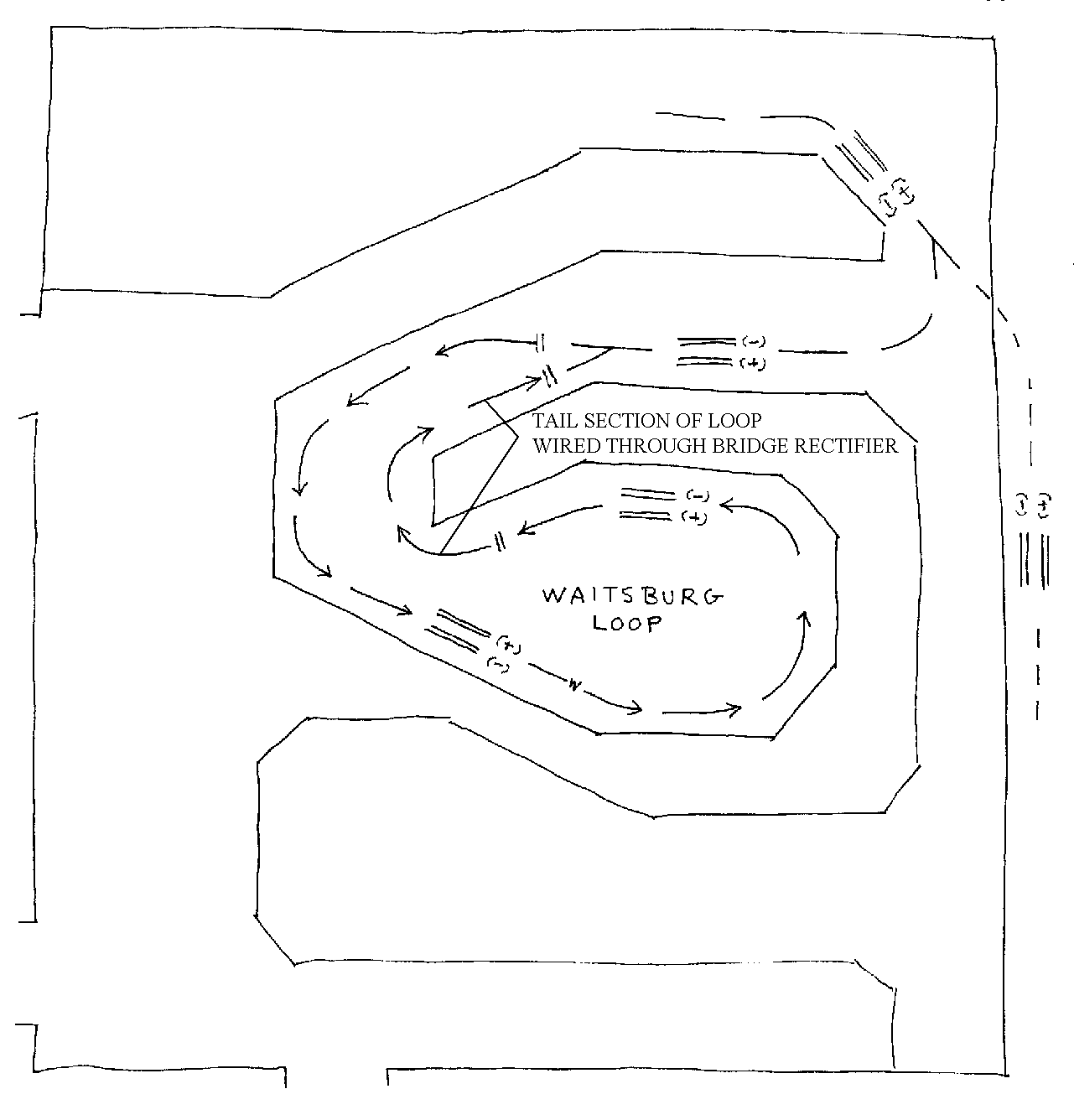
TRACK POLARITY WAITSBURG RETURN LOOP
2. CAB CONTROL TRACK POWER BUSS
Minimum* 16 gauge stranded wire from power supply to terminal(s)
MAINLINE CABS CAB = COLOR
A = GREEN
B = RED
C = BLUE
D = YELLOW
E = GRAY
F = BROWN
COMMON = WHITE
YARD AND BRANCH CABS CAB = COLOR
ORCHARD YARD WEST = ORANGE
ORCHARD YARD EAST = PINK
(LABELED)
WILLOW GROVE YARD WEST = ORANGE
WILLOW GROVE YARD EAST = PINK
(LABELED)
TUMWATER MINING = VIOLET (LABELED)
ELECTRIC CATENARY = RED
CASCADE TIMBER = VIOLET (LABELED)
COMMON = WHITE
The six mainline cab positive track power distribution wires plus their single common negative return wire are bundled together and distributed throughout the layout in the mainline cab buss. These are linked to the local selectors via screw type terminal blocks with solderless spade-clip connections.
The six secondary (yard and branch) positive track power wires are run to the necessary locations, use the same common return, and are connected via terminal blocks.
3. WIRING TO TRACKS
Minimum* 16 gauge stranded wire
Minimum* 22 gauge stranded wire for rail drops
POWER SIDE = YELLOW
COMMON SIDE = BLUE
Track power is supplied from the rotary selectors to the tracks via 16 gauge or better feeder wires which run the length of the track.
* Note: Though the layout has been previously wired to lesser standards (typically using #16-22 gauge wire) we are establishing the following standards for any new installations or retrofits in advance preparation for DCC.
| Short drop wires no longer than 1 ft. | #22 gauge | |
| Feeder wires no longer than 10 ft. | #16 | |
| Feeder wires no longer than 50 ft. | #14 | |
| Feeder wires longer than 50 ft. | #12 |
22 gauge drop wires connect the feeder wires to every piece of rail. Their length should be kept to a minimum, ideally no more than 1 foot.
Power routing, explained fully in Section VIII.F, should adhere to these basic rules as well.
4. TURNOUT ACTIVATION
Minimum 18 gauge stranded wire
POS. SUPPLY BUSS = GREEN
NEG. RETURN BUSS = BLACK
Minimum 18 gauge stranded wire
POS. SUPPLY TO TOGGLE = RED
TOGGLE TO SW. MOTOR = RED
SW. MOTOR TO NEG. RETURN = BLACK
Supply and return alternating current (AC) power for the switch machines is supplied throughout the layout via buss wires.
These are connected to the machines through toggle switches and circuits as explained in Section VIII. of this manual.
The connections are hard wired (soldered).
5. TURNOUT INDICATION
Minimum 22 gauge stranded wire
LEFT RELAY TO LEDS = WHITE
RIGHT RELAY TO LEDS = ORANGE
POS. SUPPLY TO LEDS = RED
POS. SUPPLY BUSS = GREEN
NEG. RETURN BUSS = BLACK
Light emitting diodes (LED) on the control panels are used to indicate the direction turnouts are thrown.
One side of the LEDs are connected to the AC power buss (same as used for switch activation) through a 390 ohm resistor. The other side is connected to the return AC power buss utilizing the reversing diodes of the switch machine to indicate the throw. These connections are made on the lower relay contacts. Bi-LEDs are employed which glow red or green depending upon the polarity.
The connections are hard wired (soldered).
See Section VIII.D of this manual.
6. TURNOUT FROG POWER
Minimum* 22 gauge stranded wire
POWER SIDE OF TRACK = YELLOW (ORANGE)
COMMON SIDE OF TRACK = BLUE (WHITE)
SWITCH FROG = WHITE/YELLOW stripe (RED)
All turnout frogs are electrically isolated and supplied with power according to the position of the turnout via switch machine relay contacts as explained in Section VIII. of this manual.
22 gauge wires should connect the feeder wires (rail) to the relay tabs. A 22 gauge drop wire connects the relays to the turnout frog. Their length should be kept to a minimum, ideally no more than 1 foot. *Otherwise, larger wires should be used. See the previous chart: I.C.3 for guidelines.
Some turnouts may still be wired with the old color code which is indicated with the old (color) in parentheses.
In some cases you may find turnouts wired without any color code! Green telephone wire was used for everything. If you are chasing trouble you will have to physically trace each wire end to end to determine their function. It will make a firm believer in color codes out of you.
7. THROTTLE CONTROLS
Our conventional DC walk-around memory throttles are interfaced through standard telephone modular jacks placed conveniently throughout the layout. These are commonly wired using standard telephone company (telephony) cabling practices including 3 pair and 25 pair 24 gauge solid hard wired cables and components with a strict adherence to the standard telephony color code.
Refer to Section V. of this manual for full details.
8. SIGNALING
Currently there is no signaling wired to the layout.
Should they be installed all aspects shall be covered in Section XII of this manual.
9. STRUCTURE LIGHTING AND ACCESSORIES
Currently there is no common structure and miscellaneous lighting wired to the layout.
Should they be installed all aspects shall be covered in Section IV.F of this manual.
10. OTHER
Other miscellaneous wiring should be covered in Section XIII of this manual.
D. STANDARD LAYOUT WIRING SCHEMATICS:
Wiring schematics and diagrams are presented throughout this document for the various elements.
They will be labeled with the corresponding Section (Roman) number, Sub-Section (Alpha), number (n), and revision (alpha) of this manual.
For example, a diagram for this section might be labeled: I.D.1.a.
Track Schematic (TS) drawings are to be found in Section II. LAYOUT.
Comprehensive layout schematics are being prepared. They will be placed in Section XIV. LAYOUT SCHEMATICS, including Electrical Schematics (ES) and Standardized Charts (ES-C) for switch machine, track power and throttle control.
|
To Next Section - II. Layout - General Return to Electrical Manual Index |